
Here in this Tutorial you are going to learn about the 3D modelling process in the ANSYS Software.
Inputs Given
Type of Element : Brick Solid 45
Model Given :
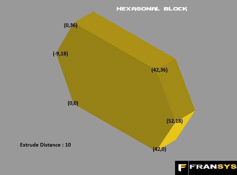
Extrude Distance : 10
From this Model we have to find the co-ordinates(i.e.)x,y values with respect to origin.
*Note : Since Keypoints form the basis of any model which is modelled in ANSYS.
KeyPoints Co-ordinates :
Just find the values and keep it aside. Check the values with the thing given below:
K.P.No. X Value Y Value
1 0 0
2 42 0
3 52 18
4 42 36
5 0 36
6 -9 18
Lets start from Scratch.
First open the ANSYS Product Launcher as shown in the Screen Shot.
Start< All Programs< ANSYS 10.0 Folder< ANSYS Product Launcher
*Note : You can also start the ANSYS by double Clicking the ANSYS Icon but by opening the ANSYS Program through ANSYS Product Launcher has many advantages like Setting of Working Directory and Setting JobName very easily. But the another method as specified latter will make the setting of working directory, JobName a little bit complex
Step 1 : Now Set a working Directory and Set JobName as you like else type "Hexagonal Block" and click run at the bottom of the Product Launcher Window.
Step 2 : Click Preferences in the ANSYS Main Menu(Left Side tab with white background) and check the Structural checkbox and click OK

Step 3 : In the ANSYS Main Menu click Preprocessor< Element type < Add/Edit/Delete and after a window comes like the one shown below(Pic2), click Add and you will get a new window in the select Solid in one window and Select the Brick 8 Node 45 in the adjacent tab after scrolling as shown in the picture and click OK and Click Close in the previously opened Window

Step 4 : Now Click Preprocessor< Modeling < Create < Keypoints < In Active CS and you will get a window like the one which is shown in Picture below

Step 5 : Now Dont type anything in the Keypoint Number Tab since ANSYS automatically numbers it as 1 after you complete the X and Y values.
Step 6 : First click Apply without giving any values in any of the tabs.
* Note : ANSYS assumes the value as zero for blank Spaces in the values Tab. We are doing it here since we got X=0 and Y=0 for Keypoint Number
Step 7 : Without filling the Keypoint Number type 42 in X and 0 in Y and click Apply.
Step 8 : Similarily upto 5th keypoint click Apply after giving X and Y values but for the 6th Keypoint type -9 for X and 18 for Y and click OK instead of Apply as you did in Previous cases since this is the Last Point.

*Note : In ANSYS a command should be terminated with OK only. If you use the Apply option there too after that click Cancel. Instead if you click OK after Apply after the Last Point, another point is created at the same place.
Step 9 : After Completing the Step 8 you will get the following Output.

Step 10: Now Click Preprocessor < Create < Lines < Lines < Straight Line and you will get a following window. Also see what the Command prompt is telling as in screenshot. (Pick or Enter end Keypoints of Line)
Step 11: Pick any two nearby points (Example: Keypoints 4 and 5) and you will get a Line between the two keypoints. Similarily Join all the Keypoints to form a Hexagon shape as shown below.

Step 12: Now, Go to Preprocessor< Modeling< Create < Areas< Arbitrary< By Lines and a window comes up as shown below. Click Loop Radio Button in that window and click a Line in the Drawing you have drawn and you will see all the Lines are high lighted as a whole loop and finally click OK.

Step 13: You will get a Blue Coloured Hexagon which is an AREA
Step 14: Now Goto Preprocessor< Modeling< Operate< Extrude< Areas< Along Normal and you will get a Window. Now click on the area formed and press apply, then another window shows up as below and enter a value 10 in the Length of Extrusion and click OK.

Step 15: Hexagonal Block is created finally, Click on the Isometric View Icon on the Left Side of ANSYS Environment. It is Highlighted in Red Box in the Screen Shot below.

Above is the final Output for the above steps. You completed the task rightly. Congrats. Save the Database and Exit.
Hope you made the Model. Queries are invited via Comments session Below or contact Us @ galacticmech@gmail.com or arulfrances@gmail.com
Related Tags :
No comments:
Post a Comment